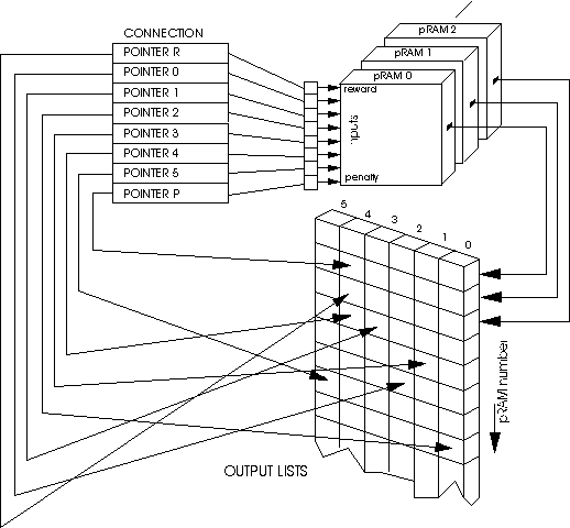

A Connection Pointer is a 12 bit binary number which defines the device location and the internal address of the data source. The definition of a Connection Pointer is shown in the following table.
| Bit | 11-8 | 7-0 |
|---|---|---|
| Function | Device Location | pRAM number or External input number |
Definition of a Connection Pointer
Bits 0 to 7 specify the pRAM number within the module if the Device Location is set to be a pRAM Module or the external input number if the Device Location is set to be an External Input.
The Device Location defines the source of the data for that input which is one of the following: the pRAM-256 Module itself, an adjacent module, an External Input, Vcc or GND. Vcc and GND allow a constant '1' or '0' to be presented to any pRAM input.
| Bit | Bit | Bit | Bit | Data Source |
|---|---|---|---|---|
| 11 | 10 | 9 | 8 | |
| 0 | 0 | 0 | 0 | Local Chip |
| 0 | 0 | 0 | 1 | North Chip |
| 0 | 0 | 1 | 0 | East Chip |
| 0 | 0 | 1 | 1 | South Chip |
| 0 | 1 | 0 | 0 | West Chip |
| 0 | 1 | 0 | 1 | GND |
| 0 | 1 | 1 | 0 | Vcc |
| 0 | 1 | 1 | 1 | Global REWARD |
| 1 | 0 | 0 | 0 | Global PENALTY |
| 1 | 0 | 0 | 1 | Negated Local Chip Data |
| 1 | 0 | 1 | 0 | Negated North Chip Data |
| 1 | 0 | 1 | 1 | Negated East Chip Data |
| 1 | 1 | 0 | 0 | Negated South Chip Data |
| 1 | 1 | 0 | 1 | Negated West Chip Data |
| 1 | 1 | 1 | 0 | External Input |
| 1 | 1 | 1 | 1 | Negated External Input |
Definition of the data source in a Connection Pointer